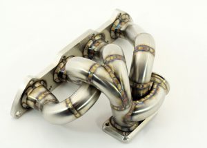
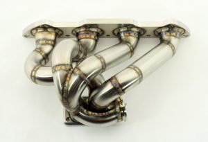
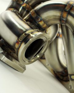
Designing and creating a manifold has always been intriguing. In the initial phase, there is a clean palate – there is an available opportunity to craft the manifold around specific needs and wants. With it comes significant trial and error in figuring out what works and what doesn’t, and creating something that’s both aesthetically appealing and efficient. In the end, if done correctly, you wind up with something that is memorable and a piece of art – whether it is by function or form, but hopefully both.
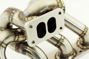
In the creation of the original piece back in 2010, the only tools used were a drill press, angle grinder, Sawzall, die grinder, and miscellaneous hand tools. The welder was a 120v MIG weld pack. Work was slow and tedious due to the limited tools on hand but, thankfully, time was more plentiful than money. The flanges, except the head flange, were made by hand. A 1/2” plate was cut with a hacksaw for both the divided T3 inlet and 5-bolt Holset outlet. The holes were drilled and then slowly enlarged to the correct shape with a carbide burr, and the edges got ground down with the angle grinder. Tedious. Excruciatingly tedious. Each elbow and straight pipe cut had to be a little longer – just in case! – and were ground down until it fit perfectly to avoid scrapping one of the few bends that was purchased. Countless markers, cut-off discs, and saw blades were used. There was a consistent covering of metal and abrasive dust everywhere. The placement consisted of wherever the turbo would fit in the, essentially, stock engine bay (including stock fans) and held in place with shop rags and scrap metal. Figuring out one runner and then the next, contemplating the chain of events that each tiny revision set in motion. Despite the careful alignment and tweaking, each weld altered it more – this was, by far, the most frustrating part of the endeavor. The manifold was almost alive in its constant movements. Each carefully trimmed puzzle piece was shifted over just enough to cause some serious anxiety.
The collector wasn’t anything like what was previously seen personally. One section of pipe coming out of each scroll on the inlet flange, with the paired runners merging into each pipe. Essentially creating a 4-2-1 design of sorts, allowing the wastegate provisions to feed equally from each cylinder pair. The pipe size was chosen with the smallest eventual area in mind and 1-1/4” pipe size (comparable to 1-5/8″ tube size) forms perfectly to a single divided T3 inlet opening. In hindsight, this seems to be one of the key pieces in the better-than-ever results.
In order to nail down the placement and approach, the wastegate provisions were made after the much-anticipated test drive. The first steadily increasing and distinct howl of the “large” (at that time) Holset turbo excitedly came on much sooner than expected. The urgent ramp of boost was tickled as close to 25psi before needing to let off (open boost with no wastegate) and short shifted into the next gear without ever losing its effortless push of building speed. At, or before, 3000 rpm, 4th and 5th gears were showing 20+psi and 5th gear was able to cause compressor surge under power from boost coming on at such a low rpm, despite the anti-surge compressor cover. Trying to pedal the car to maintain a steady boost was immediately confirmed as a bad idea and the manifold soon came back off to make the final provisions and experience the full character of the setup.
A video (thank you to /J at EOS Performance!) just after the first test drive and before the wastegate provisions were made: https://youtu.be/4y136gTJ7jY
A run down of each gear (psi vs rpm) rounded to the nearest .5psi and 50 rpm on the original car/setup
3rd Gear:
 |
|
| PSI | RPM |
|---|---|
| 5 | 2500 |
| 10 | 2900 |
| 15 | 3150 |
| 20 | 3250 |
| 25 | 3400 |
4th Gear:
 |
|
| PSI | RPM |
|---|---|
| 5 | 2350 |
| 10 | 2650 |
| 15 | 2800 |
| 20 | 3000 |
| 25 | 3100 |
It was a pleasant surprise when there was no change in spool after the wastegate provisions were added with careful profiling of the center divider to match the base of the wastegate valve. Boost crept up to 20psi at high rpm but that wasn’t much of an issue when the goal only started there. 25psi was settled on with only four 1000cc injectors and its maiden pass was at Summit Motorsports Park for the Buschur Racing DSM and Evo Shootout in 2010 resulting in 11.2@129, far exceeding the expectations at that boost level and on street tires. 10’s were a real possibility and hadn’t been done before on an HX35 at that time.
Later passes resulted in high 10’s on street tires and a best of 135.9 mph at 30psi. A dynojet showed a very healthy power curve peaking at 511whp at the same 30psi. That graph overlaid with its previous, and healthy, 300whp+ 14b setup was eye-opening in just how little low end the turbo and manifold gave up and the monstrous bump in power and torque from 4,000rpm on. All with the exact same stock 6 bolt longblock, cam combination, and a stock intake manifold. While the 14b setup was extremely fun, it was hard to compare to the HX35 after 3500rpm and its extremely broad power band.

Going with an automatic transmission was always on the bucket list. The big question was if it would be able to light up the stock converter and launch at all. At the time, many people were under the belief that this was out of the question in anything larger than a 16g. Immediately after everything was drivable, and even before the intercooler pipes were made, a hot pipe was made using semi radiator hose and scrap bends to connect the turbo directly to the throttle body. A dark rainy night and an empty parking lot sent more boost into the engine than the brakes could handle within seconds. The turbo came alive quickly enough to easily exceed 30psi on the line with the stock converter. So not only could it get on the stall with the stock converter, it left plenty of headroom to pull timing in order to kill torque on the line to keep parts alive, and quickly ramp into full boost once the brake was released. By using this approach, the car went consistent mid 1.3’s without nitrous and without breaking parts (19 psi, between -5 and -7* of timing, and keeping below 3200rpm on the brakes for that setup for those wondering). This was after a steep learning curve and many broken drivetrain components trying to get too aggressive and actually going slower. The setup eventually went 10.08@132 at 38psi peak tapering back to around 30psi as airflow levelled off with the HX35 compressor. It could get on the stock converter soon enough, usually less than 5 seconds depending on the air quality, to be an aggressive competitor in local track events. Surprisingly, even as an auto car not set up for autocross, it was still extremely enjoyable and competitive. After the eventual upgrade to the 60mm HX40 compressor wheel, the setup still went rounds, and got up on the stall quickly and efficiently to win a pro-tree event.

Now referred to as “The Auto Car” since we have so many red ones, the setup has constantly been tweaked and changed but after 10+ years, the manifold is what defines it. It’s what has made it an incredible street car – manual and auto, with very basic supporting modifications – that still lays down some damn good times for a 54mm turbo at the track.
One of the natural progressions after taking over the Evo and DSM side of things for Ron Shearer at Shearer Fabrications was to replicate the manifold that has served and performed for all these years showing what the twin scroll housing is capable of. There were many occasions after building the first where people were interested purchasing but the amount of time involved made it simply not feasible. Even with time being put full-time into building manifolds and now having the tools to do so efficiently, the twin scroll T3 manifold doesn’t follow typical manifold fabrication approaches – requiring over 15 separate fixtures and guides to make it consistently repeatable and true to its form. Small updates were made to allow smoother transitions, equalize runner lengths, step up to a larger 44mm MVR wastegate (still just one well-placed wastegate divided and profiled up to the valve’s seat), and optimize the placement for all turbine housing options including being 2g 7-bolt friendly. The end result is a compact true twin scroll T3 manifold that puts function over form and area under the power curve.


